Machine-readable: manifest · index · English Markdown
Draft translation: this English page is available for review and is not yet the production default.
Configure scan data
Map Configurator associates visual observations from the scan video with measured site data, giving the map a trustworthy real-world size, origin, and axis orientation. Portal loads the parsed panorama frames directly; the video is not uploaded again.
GCP stands for Ground Control Point. Despite the name, a GCP does not have to be on the floor. A doorway corner, wall-floor intersection, or fixed structural corner is valid when it cannot move, can be identified accurately in several frames, and has known site X, Y, and Z coordinates.
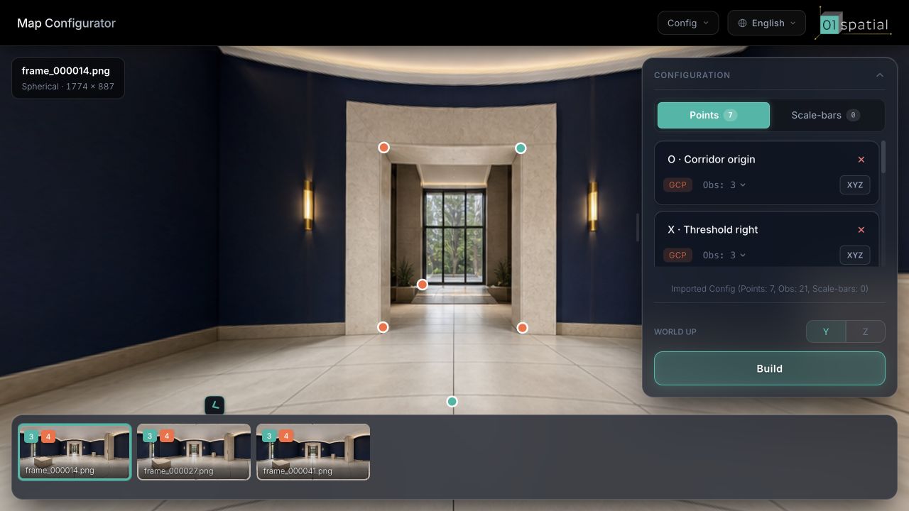
A manually configured build requires at least three usable, non-collinear GCPs. For production, use four to five non-coplanar GCPs spanning left/right (X), low/high (Y), and near/far (Z). Every GCP needs X, Y, and Z coordinates in meters and observations in at least two different panorama frames. Tie Points and Scale Bars are optional enhancements; they cannot replace GCPs.
Understand the three constraint types
| Constraint | Required value | What it solves |
|---|---|---|
| GCP | X, Y, and Z in meters | Defines the real scale, origin, and coordinate orientation |
| Tie Point | No coordinate | States that multiple frames see the same static point and strengthens connections across rooms, doors, or corridors |
| Scale Bar | Real endpoint distance in meters | Adds an independent measured-distance constraint |
A GCP is a complete coordinate anchor. A Scale Bar supplies length only. A Tie Point supplies cross-frame correspondence only. The three types are not interchangeable.
1. Open configuration and choose the coordinate frame
- Wait until the map status in Spatial Maps becomes Parsed.
- Select Configure on the map card to open Map Configurator.
- Choose a frame from the strip below the panorama. Drag the main view to look around; select Full Resolution at the top right when precise placement is needed.
- Choose the up axis under WORLD UP:
- Y is common in AR and real-time 3D. With the origin on the floor, floor points usually have
Y = 0. - Z is common in surveying and CAD. With the origin on the floor, floor points usually have
Z = 0.
- Y is common in AR and real-time 3D. With the origin on the floor, floor points usually have
- Confirm that this convention matches downstream Space Studio content or existing survey coordinates. Do not change conventions after configuration begins.
2. Add the first GCP
Create the point
- Find a measured, fixed geometric corner. Prefer an intersection formed by walls, the floor, and a permanent architectural element; it is easier to identify repeatedly across frames than an arbitrary surface position.
- Right-click the exact location and select Add Point.
- The new point appears in the right-side Points list and on the current frame.
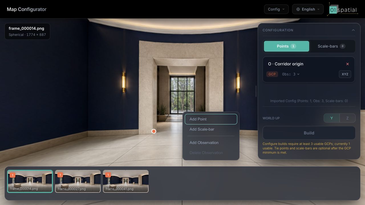
Place the target precisely on the fixed doorway-and-floor corner, then select Add Point. Do not use shadow boundaries, reflections, highlights, plants, or movable objects as control points.
Enter a name and coordinates
- Give the point a recognizable name such as
O · Corridor origin. - Select XYZ on the point row.
- Enter X, Y, and Z in the chosen world frame. Always use meters.
- Verify signs and decimal places, then select Save. The point type becomes GCP after coordinates are present.
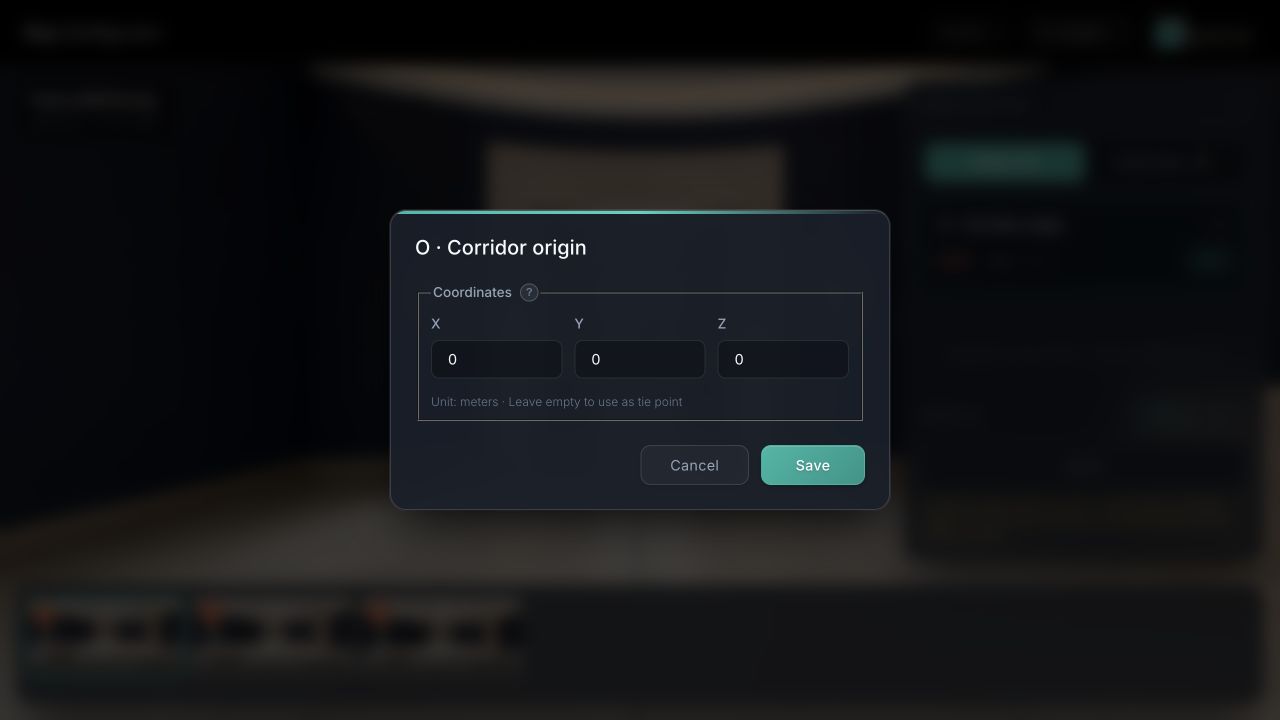
The example defines the wall-floor corner as world origin O = (0, 0, 0). Complete X, Y, and Z to make the point a GCP. To create a Tie Point instead, leave all three coordinates empty.
Add observations in multiple frames
- Select another frame in the bottom strip and confirm that it clearly sees the same physical point.
- Right-click the exact same location, expand Add Observation, and choose the point you created.
- Complete observations in at least two different frames. A clear third observation with useful viewpoint separation is often more robust.
- Expand Obs on the point row and verify every frame name. If a placement is inaccurate, remove that observation and add it again; do not move it to an approximate location.
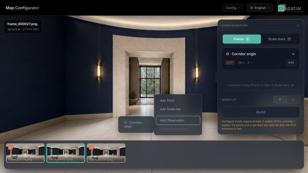
Right-click the same physical corner in a new frame, expand Add Observation, and select the existing GCP.
3. Build a complete GCP coordinate skeleton
Repeat point creation, coordinate entry, and observation placement. The system minimum is three usable, non-collinear GCPs. To constrain the full 3D space, production projects should use four to five GCPs, with at least four being non-coplanar. Every GCP must satisfy all of the following:
- X, Y, and Z are finite values in meters.
- Observations exist in at least two different panorama frames.
- Every observation lands on the same static physical point.
- At minimum, three GCP world coordinates do not lie almost on one line.
- Prefer a set that spans left/right, low/high, and near/far instead of lying on one wall, one floor, or any other single plane.
The doorway example below uses four corners to build an explicit O-X-Y-Z coordinate skeleton in a Y-up frame:
| Point | Example coordinate (m) | Direction constrained |
|---|---|---|
| O · Corridor origin | (0, 0, 0) | Wall-floor origin |
| X · Threshold right | (2.4, 0, 0) | X across the threshold |
| Y · Jamb upper-left | (0, 2.8, 0) | Y up the vertical jamb |
| Z · Corridor far-left | (0, 0, 5.6) | Z into the corridor |
These four points enclose a 3D volume instead of forming a rectangle on one wall. In a large site, add a fifth GCP at the far end for redundancy. The numbers illustrate the coordinate relationship only; use measured site coordinates and never alter survey values merely to make them axis-aligned.
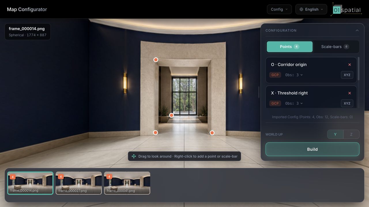
The four orange GCPs occupy the near lower-left, near lower-right, near upper-left, and far corridor corners. Together they span X, Y, and Z rather than one plane.
4. Add a Tie Point
Tie Points are useful at doorways, long-corridor corners, repeated-texture areas, or transitions between connected rooms. They need no site coordinate; they only state that several frames show the same static feature.
- Choose a distinctive, stationary geometric corner that is clearly visible from both sides of the connection—for example, an upper corner of a fixed plinth, a crossing of two tile grout lines, or a doorway-lintel corner. Do not click an arbitrary position on a plain wall, floor texture, or edge.
- Right-click and select Add Point.
- Enter a name, but leave X, Y, and Z empty. The type in the right panel should read Tie Point.
- Switch to a frame from the other side of the connection and use Add Observation on the same physical location.
- Add at least two observations and expand Obs to verify them individually.
- Keep only high-confidence correspondences. An incorrect Tie Point is more damaging than a missing one.
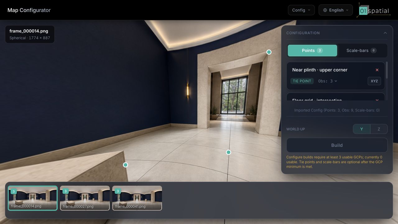
Every teal Tie Point should land on a real corner that can be selected repeatedly across frames; distribute them across weak transitions instead of clustering them in one small area.
5. Add a Scale Bar
Use a Scale Bar when the site contains a reliably measured distance. Prefer a fixed segment with unambiguous endpoints that can be identified from multiple positions.
- Measure the straight-line distance between the two endpoints on site and record it in meters.
- In a panorama that clearly shows both endpoints, right-click and select Add Scale-bar.
- The right-click position becomes endpoint A; accurately select endpoint B in the same frame.
- Open Scale-bars on the right and enter a clear name and the measured length.
- Switch to other frames and add paired observations for endpoints A and B. Each endpoint should be visible in at least two different frames.
- Return to Scale-bars and confirm that the status is Ready and the length is correct.
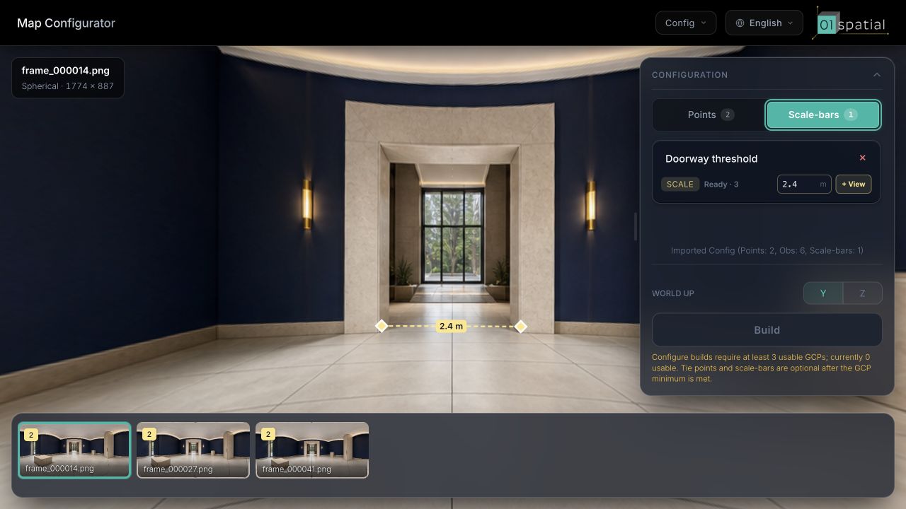
The example uses a measured 2.4 meter doorway threshold. Confirm that the yellow line joins the intended physical endpoints and reads Ready in the panel. A Scale Bar cannot replace GCPs.
6. Pass the build-readiness check
The status in the right panel states what is missing. Before selecting Build, confirm that:
- At least three usable, non-collinear GCPs have valid metric XYZ coordinates.
- Every GCP has observations in at least two different panorama frames.
- Production projects preferably use four to five non-coplanar GCPs spanning left/right, low/high, and near/far.
- GCPs do not all lie on one wall, one floor, or in one small corner.
- Every Tie Point has at least two observations of the same static feature.
- Every Scale Bar intended for the build reads Ready and uses meters.
- WORLD UP matches the project coordinate convention.
- No observation lands on a blurred, occluded, or incorrect physical location.
When you select Build, Configurator submits only the constraints and starts mapping. The parsed panorama frames remain on the server and are not uploaded again.
Common questions
There are enough GCPs, but Build is still disabled
Check that every GCP has at least two frame observations and that the minimum three points are not almost collinear. Coordinates alone do not make a point usable. Four to five non-coplanar points are a quality recommendation; they do not change the system minimum.
The same point is difficult to confirm in another frame
Switch to Full Resolution and inspect it closely. If it is still uncertain, remove that observation and choose a more stable physical feature; do not estimate the location.
How many Tie Points should I add
Add them only at weak connections. A few high-quality Tie Points at doorways, corners, or room transitions are usually more useful than scattering points uniformly across the map.
After configuration passes the check, continue to Build and validate the map.