Machine-readable: manifest · index · English Markdown
Draft translation: this English page is available for review and is not yet the production default.
Configure standard-camera scan data
Map Configurator loads frames extracted from the video and preserves their recorded orientation. Mark surveyed, fixed corners across several frames to give the map the correct real-world size, origin, and orientation. The video does not need to be uploaded again.
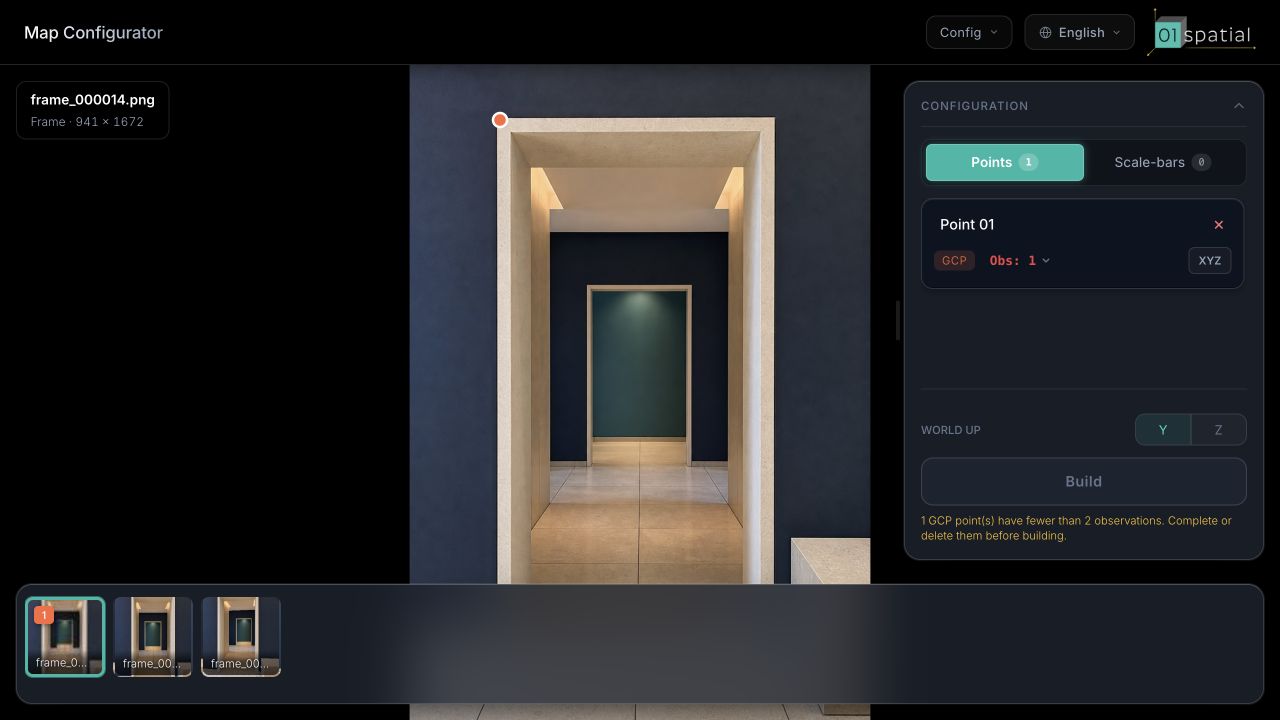
GCP stands for Ground Control Point. Despite the name, a GCP does not have to be on the floor. A doorway corner, wall-floor intersection, or fixed structural corner is valid when it can be identified in several frames and its X, Y, and Z coordinates have been measured.
A manual configuration requires at least three usable, non-collinear GCPs. For production, use four to five GCPs, with at least four non-coplanar points spanning the left/right, low/high, and near/far directions. Every GCP needs accurate observations in at least two different frames.
Understand the three constraint types
| Constraint | Required input | Purpose |
|---|---|---|
| GCP | X, Y, and Z in meters | Defines real-world size, origin, and coordinate orientation |
| Tie Point | No coordinates | Links the same fixed corner across frames and strengthens regional connectivity |
| Scale Bar | Measured endpoint distance in meters | Adds an independent distance check |
They are not interchangeable. A GCP supplies a complete coordinate; a Tie Point supplies correspondence only; a Scale Bar supplies length only.
Marker rule: every point must coincide with a repeatable fixed corner. Place GCPs and Tie Points on wall-floor corners, doorway corners, fixed cuboid corners, or intersections of two tile-grout lines. Both Scale Bar endpoints must also use corners of this kind. Never click an arbitrary position on a flat surface, texture, shadow edge, or line segment.
1. Open the configuration and choose the world frame
- Wait until the map is Parsed in Spatial Maps.
- Select Configure on the map card.
- Choose a frame from the strip below the viewport. The center shows the frame in its recorded orientation; prefer a sharp, unobstructed view of the corner you need to mark.
- Under WORLD UP, choose the vertical axis. AR and real-time 3D projects commonly use Y; survey or CAD projects may use Z.
- Match the choice to Space Studio content or existing survey coordinates. Do not change it after marking begins.
2. Add the first GCP
- Find a measured, immovable geometric corner with a crisp boundary.
- Right-click the corner and select Add Point.
- Give it a recognizable name such as
O · Entrance origin. - Select XYZ and enter the surveyed X, Y, and Z values in meters.
- Check signs and decimal places, then select Save.
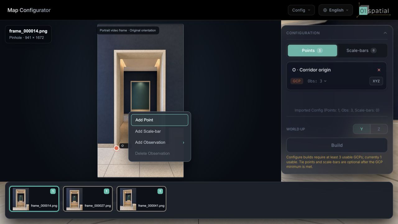
Place the marker on the physical corner—not on a shadow, reflection, highlight, or movable object.
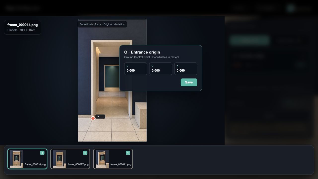
The example defines the entrance corner as O = (0, 0, 0). The point becomes a GCP after all coordinates are present.
Add observations in more frames
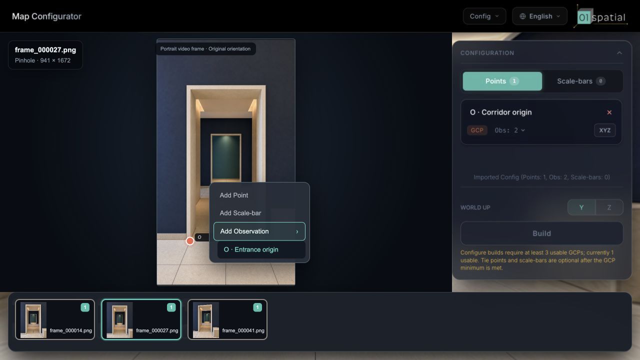
- Switch to another frame that clearly shows the same corner.
- Right-click the exact same physical location, expand Add Observation, and choose the existing GCP.
- Add at least two different frames. A third sharp frame with useful viewpoint separation usually improves reliability.
- Expand Obs and inspect every entry. Delete and re-mark an inaccurate observation rather than moving it to an approximate location.
3. Span the 3D space with GCPs
Repeat point creation, measurement, and observation marking. A clear pattern is an O-X-Y-Z skeleton: one origin, one left/right point, one low/high point, and one near/far point. Do not place every GCP on one wall, one floor, or one small area.
This example uses Y-up, so X, Y, and Z correspond to left/right, low/high, and near/far. If the project uses Z-up, follow the project coordinate convention instead of copying the example coordinates.
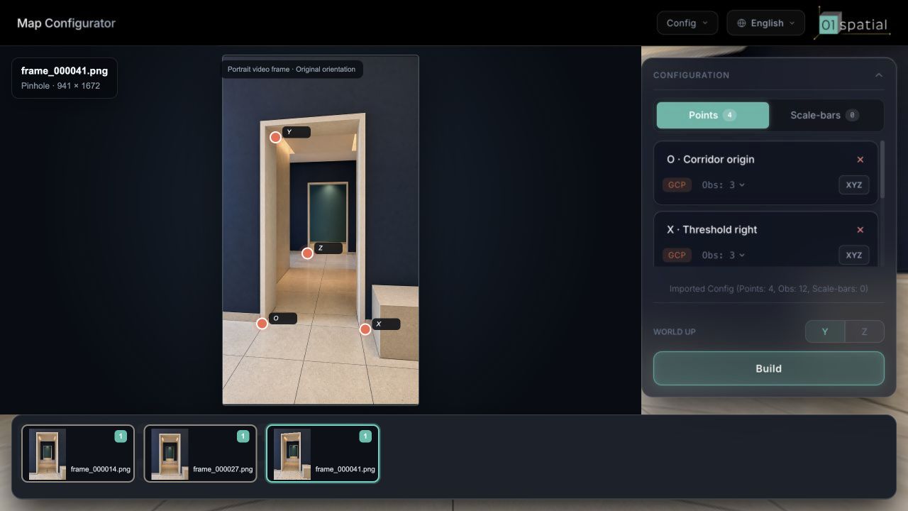
Every GCP must satisfy all of the following:
- X, Y, and Z come from site measurements in meters.
- The point is accurately marked in at least two different frames.
- Every observation identifies the same static physical corner.
- At least three GCPs are not almost collinear.
- For production, at least four GCPs are non-coplanar and span the full 3D space.
4. Add Tie Points where needed
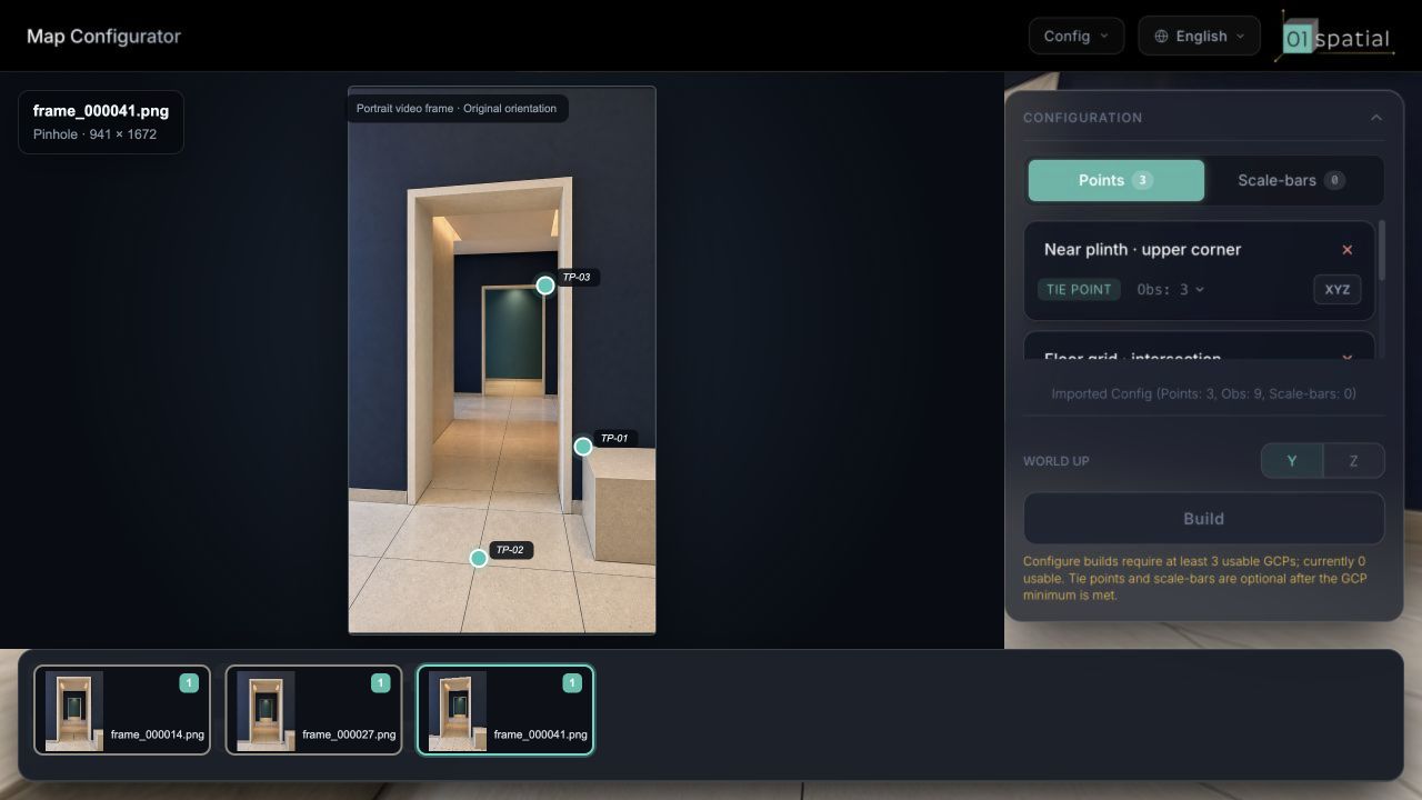
Tie Points strengthen connections where doors, corners, or connected rooms have limited shared coverage.
- Choose a fixed corner visible from both sides, such as a tile-grout intersection, fixed plinth corner, or doorway corner.
- Select Add Point, enter a name, and leave X, Y, and Z empty.
- Use Add Observation on the same corner in other frames.
- Keep at least two accurate observations. Do not add a point if the identity is uncertain.
5. Add a Scale Bar where needed
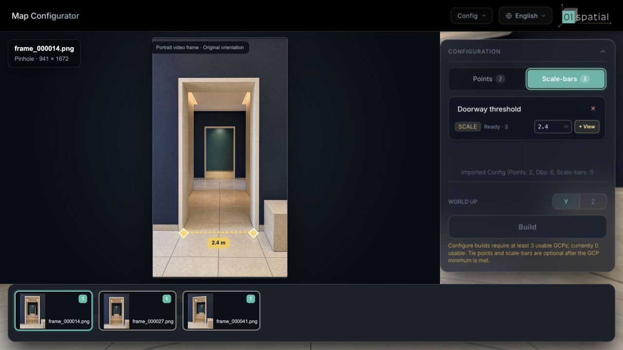
Use a fixed segment with clear endpoints and a reliable site measurement as an independent check.
- Measure the straight-line endpoint distance in meters.
- Right-click a frame that shows both endpoints and select Add Scale-bar.
- Mark endpoints A and B precisely, then enter the name and measured length.
- Add corresponding endpoint observations in other frames.
- Confirm that the right panel reports Ready.
6. Check before building
- At least three usable, non-collinear GCPs have valid XYZ coordinates.
- Every GCP has accurate observations in at least two different frames.
- Production projects preferably use four to five GCPs spanning 3D space.
- Every Tie Point identifies the same fixed corner.
- Every Scale Bar reports Ready and uses meters.
- WORLD UP matches the project convention.
- No observation lands on blur, occlusion, or a movable object.
When the checks pass, select Build and continue to build the standard-camera video map.